Inspecting valve guides and clearance
Valves and valve guides are exposed to high temperatures and pressures which leads to wear of their surface. Therefore, it is necessary to inspect the valve guide. If they wear out a lot, the engine oil passes between the guide wall and the valve stem, entering the combustion chamber. If the wear is large, then the valve has too much lateral travel in the guide so that the valve head does not close properly and the tip does not close on the valve seat. This leads to leakage of the mixture from the compression volume next to the valve and then to the absence of ignition in that cylinder. The valve and valve guide are checked with a micrometer or comparator.
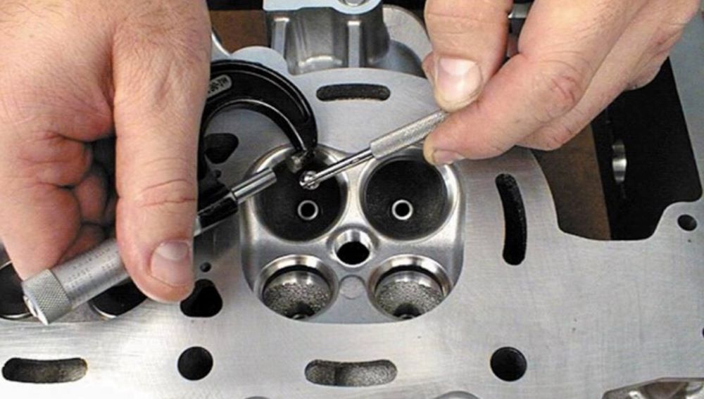
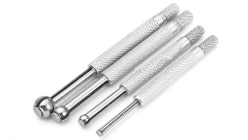
A ball gauge is used to measure the top, center, and bottom of the valve guide for measuring with a micrometer. The ball of the meter is placed in the guide and spread until both sides of the meter touch the inside of the guide. It is then removed from the guide, and the diameter is measured with a micrometer and recorded. Three measurements are performed for each guide. The reading in the middle is subtracted from the final readings to determine the narrowing of the guide. The smallest value (usually in the center of the guide) determines the inside diameter.
Telescopic gauge
The diameter of the valve stem is also measured and recorded. If the diameter of the valve stem is within the specifications, the clearance is calculated. The difference between the guide and the valve stem is the valve clearance. The clearance should be within the manufacturer’s specifications.
A comparator is used to measure valve clearance. The measurement is performed when the valve is in the valve guide and in the fully open position. The comparator indicator is placed on the cylinder head near the valve head. The comparator needle is placed on the valve head to measure the lateral movement of the valve. The valve moves laterally by observing the movement of the stroke value on the comparator indicator. The maximum measured stroke is the valve clearance and is compared to the specifications.
To inspecting valve guides and clearance, follow these steps:


