Alternator rotor testing
Testing the alternator rotor involves a visual inspection of the condition and an electrical check of the correctness of the rotor windings.
First, a visual inspection of the condition of the rotor is performed. The rotor windings are carefully inspected for discoloration, overheating, or burning. If these changes are noticed, the rotor is not good. If there are scratches on the outer surface of the rotor jaws, it means that the rotor is touching the inside of the stator during rotation. The cause may be worn bearings or a bent rotor shaft. The condition of the sliding rings is also carefully inspected. They should be smooth, clean, and undamaged.
When the rotor passes the visual inspection, the electrical testing of the windings continues. A multimeter or an ohmmeter is used to measure the coil resistance. Typical winding faults can be open-circuit, short-circuit, or short-to-ground.
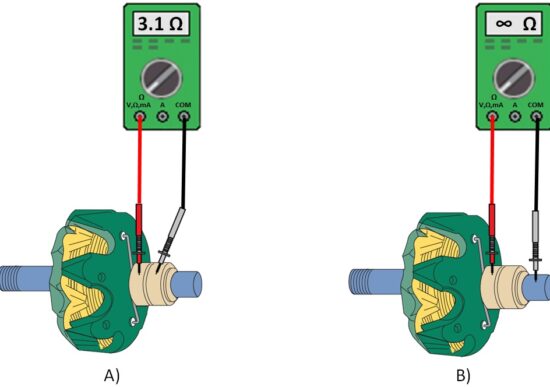
The rotor winding resistance is measured between the slip rings (A). The correct, expected rotor winding resistance value is read from the information system for a given alternator. If the data is unavailable, typical values of 2.4-3.5 Ω or 3-6 Ω depending on the type are used.
When the measured resistance is within the specified values, the rotor is correct.
If the measured resistance is infinite, the winding is faulty and the rotor needs to be replaced.
If the resistance is less than the minimum required value, there is a short circuit and the rotor is faulty. In this case, the rotor draws more current, creates a strong magnetic field, and the alternator overheats.
If a higher-than-expected resistance is measured, there is a transient resistance due to poor solder or corrosion. Cleaning or soldering the joint can often eliminate this irregularity. Otherwise, the rotor is defective and needs to be replaced.
Testing windings for open-circuit, short-circuit (A), and short-to-ground (B)
The windings must be well insulated from the ground, that is, the housing and rotor shaft. When the insulation of the winding is damaged, windings are short-to-ground. The test is performed when one measuring pipette of the ohmmeter is placed on the slip ring and the other on the rotor shaft (B). With a correct rotor, the value of mass resistance is infinite. Any other resistance reading means that there has been an insulation breakdown to the ground, and the rotor needs to be replaced.
To perform an alternator rotor winding test, follow these steps:


