Testing temperature sensor
Diagnostics and measurements are used to test the temperature sensor. Temperature sensors are thermistors that change their resistance as the temperature changes. The use of NTC resistors on vehicles is frequent. There are examples (exhaust gas temperature sensors) where PTC resistors are also used. Regardless of whether the temperature sensors measure the temperature of the engine, intake air, outside air, cabin air, oil, etc., they all have the same correctness check procedure.
When the malfunction of the temperature sensor is suspected, the system diagnostics is performed first by reading the fault codes and the current actual value. Control units (ECU) receive data on the current temperature of the monitored area from the sensor. In addition, they check the electrical integrity of the sensor itself to ensure that there is no open circuit in the plus or minus line or a short circuit. When the ECU detects an electrical malfunction of the temperature sensor, it stores the fault code and lights the malfunction indicator lamp on the dashboard. In most cases, after a detected malfunction (open or short circuit) in addition to the fault code, the ECU takes the memorized substitute value for the temperature and continues with the system management. The only thing EUJ cannot recognize is when the temperature sensor starts to “lie” and sends the wrong data for the temperature of the measuring area. Therefore, in addition to diagnostics, it is necessary to perform additional measurements on the sensor.
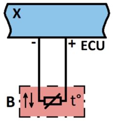
Temperature sensor circuit
The next step in determining the malfunction is to get to know the electrical connection diagram, the position of the sensor on the vehicle, the procedure and the necessary measurement values for testing. The first test refers to checking the ECU’s power supply to the sensor. At the same time, we test the correctness of the connection cables between the ECU and the temperature sensor. We remove the socket from the sensor, activate the power supply by making a contact and measure the supply voltage at the socket connections. Most often, the supply voltage of the sensor from the ECU is 5 V. If we find that there is no power or the voltage is of a different value, we approach the check from the socket to the ECU. The cause of the lower voltage value can be a bad contact on the sensor socket or the ECU. The absence of voltage can cause a break in the plus or minus lines, a short circuit, or a break in the power supply from the ECU.
If there is power at the socket connections, we proceed to check the temperature sensor. For each sensor from the information system, we receive resistance and/or output voltage data depending on the temperature in the form of a table or graphic dependence. For different temperatures, we measure the output resistance and/or voltage on the sensor and compare the obtained values with those required from the information system. If the values differ, it means the sensor is “lying”, and we replace it with the correct one.
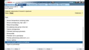
Engine coolant temperature sensor
Finally, through the diagnostic device, we check the change in the output signal with the temperature change. Also, we can check the accuracy of replacement data in ECU by simulating open and short circuits. We read the data for the replacement values from the information system for the given temperature sensor.
To test the temperature sensor, follow these steps:


