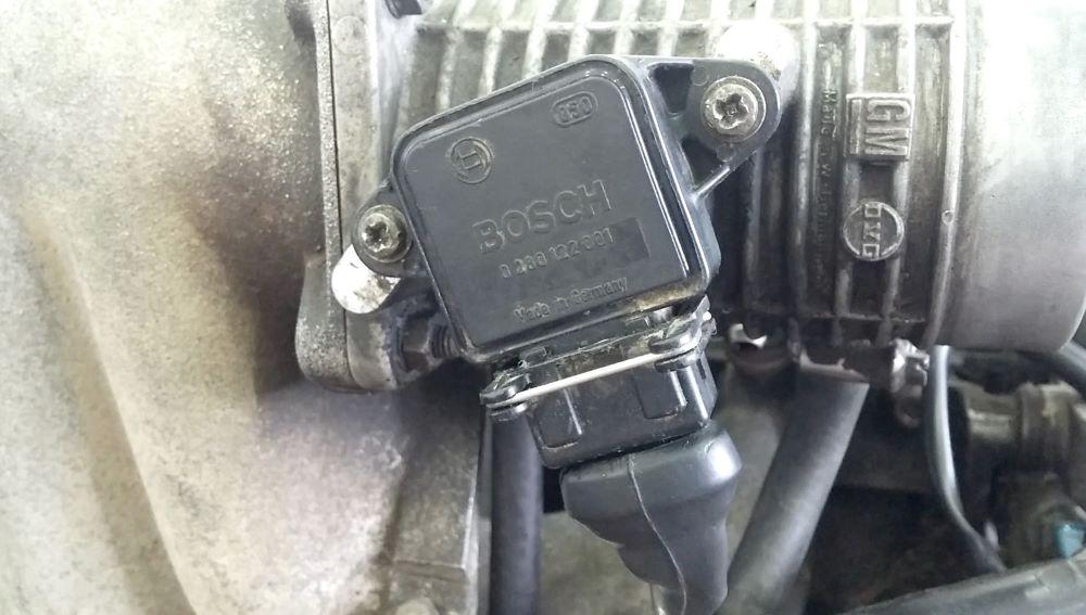
Throttle valve sensor test
The throttle valve sensor measures the angular position of the throttle valve and forwards the data as a voltage value to the control unit for further processing. The most common symptoms of a bad or misaligned sensor are engine stalling, incorrect idle speed, and hesitation and stalling during acceleration. The fuel/air mixture is out of tune because the ECU is not receiving the correct data from the throttle position sensor. If these problems occur in engine operation, it is necessary to perform test correctness of the throttle valve sensor.
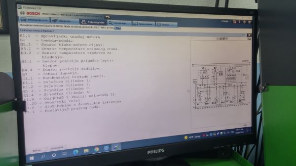
Before testing, we get acquainted with the type, electrical connection diagram, connection arrangement and actual values for a correct throttle valve sensor.
There are several types of throttle valve sensors.
The oldest type is the throttle position switch (a). It contains two buttons and a cam on the throttle shaft. At idle, the throttle is closed, and the cam presses one button. When the throttle valve is fully open it is full load mode, and the cam presses another button. In partial load mode, the throttle is partially open. In this mode, the cam does not touch either key and both are open. The control unit receives negative voltage through the sensor switch. Based on the combination of data obtained from the ECU button, it recognizes three engine operating modes (idle, partial and full load) and can adjust the injection and engine operation accordingly.
With the development of the injection system, the ECU requires the exact position of the throttle. Instead of a button, a potentiometer (b) is built into the sensor. The potentiometer slider is on the shaft and rotates together with the butterfly. The potentiometer is supplied with a constant voltage from the ECU. The potentiometer is a voltage divider and the output voltage from the slider depends on its position, i.e. the angular position of the throttle. Based on the received data from the sensor, the ECU can calculate the exact position of the throttle.
Some sensors have a button (c) next to the potentiometer, which is activated when idling, that is when the throttle is closed.
In newer injection systems, due to the requirement that there should be no stalling of the engine due to failure of the mixture control elements, a double potentiometer (d) is installed in the throttle position sensor. They work in parallel, but if there is a failure on one, the other works properly, the ECU recognizes the error, turns on the error light, and the engine continues to function smoothly.
Different types of throttle valve position sensors
Testing the sensor as a throttle valve position switch comes down to checking the correctness of the button when we rotate the cam, the negative power supply and the correctness of the lines to the ECU.
In the case of potentiometer sensors, the power supply from the ECU to the sensor (5 V), the resistance value at the ends of the potentiometer and the accuracy of the output resistance or voltage from the slider when the throttle is closed (idle) and fully open (full load) are checked.
The initial adjustment of the idle sensor is critical. With many sensors, we can adjust this output voltage by rotating the entire sensor relative to the throttle body when the loosened retaining screws are.
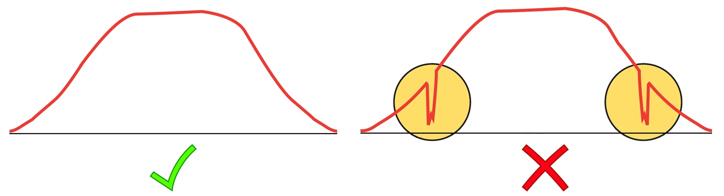
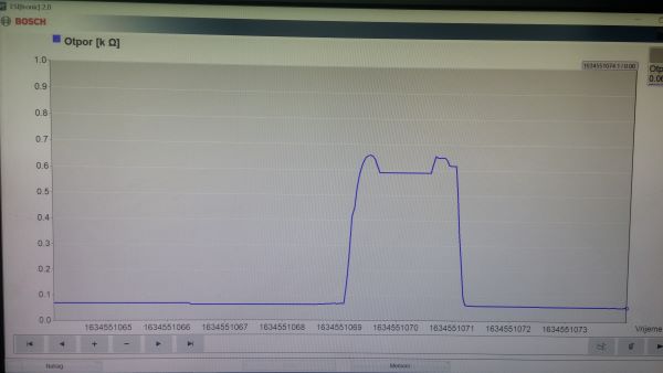
This is not enough to claim that the sensor is correct. It happens that during long-term use, the slider damages part of the resistance path of the potentiometer. Then there is an interruption of operation when the slider passes over that damage, and the ECU loses the signal from the sensor. Interruption occurs most often in the part of the lower partial load because it is the most common driving frequency. The test is performed by recording the signal from the slide when we slowly add gas to the end and back. The test lasts about 2 seconds and based on the recorded waveform we can determine the correctness of the sensor.
Recording of the sensor output signal
For sensors with a double potentiometer, the test procedure is the same, only it is performed separately for one and the other. These two potentiometers have a common power supply from the ECU.
To test the throttle valve sensor, follow these steps: