System overview
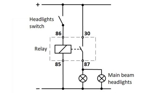
First, the correctness of the system is checked, in our case, the operation of the main beam on the vehicle. If turning on the main beam headlights switch does not turn on both lights, the electrical diagram shows that the relay is one of the possible malfunctions.
From the information system, we get to know the position of the lighting relay on the vehicle. We remove the relay from the plate and perform a visual inspection of the exterior of the housing and connectors. If the relay is visibly damaged, replace it with a new one.
Testing the relay socket on the plate
We determine the arrangement of connections (numbers) on the relay socket.
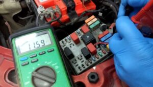
First, we check the voltage between terminals 85 and 86. We connect the voltmeter and turn on the main beam switch. If the measured voltage is 0 V, there is a fault in the power supply of the relay coil. It is necessary to carry out additional tests and determine the location of the failure. If the measured nominal voltage is 12 V, the power supply to the relay coil is correct.
Then there is a check of the main beam power supply via the relay. Short-circuit terminals 30 and 87 are on the relay socket. We turn on the main beam through. If the main beam bulbs do not light up, there is a fault in the power supply of the bulbs. It is necessary to carry out additional tests and locate the fault. If the main beam bulbs light up, the relay socket is correct, and we move on to testing the relay itself.
Testing the relay on the workbench
Relay testing is done with an ohmmeter.
First, measure the resistance of the relay coil between connectors 85 and 86. The expected resistance value is 70-120 Ω. For the exact value of the tested relay, use the information system. If the measured value is not within the specified limits, the relay winding is defective, and it is necessary to replace the relay with a new one. If the measured value is within the specified limits, the relay winding is correct.
After winding, check the entire relay. A 12 V power supply is supplied to the coils of relays 85 and 86. We connect an ohmmeter to connectors 30 and 87. If the resistance is infinite after switching on the relay, the relay is faulty and needs to be replaced. If the resistance is 0 Ω, the relay is working.
In new vehicles, it is not allowed to use a test lamp with a light bulb due to the possible transfer of high current and damage to the ECU. Take care of the pinout when testing.


