Alternator Diode Testing
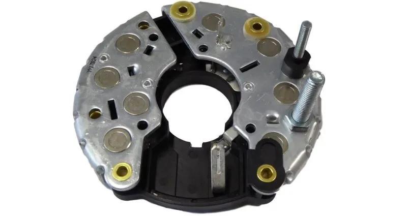
Alternator diode testing is a procedure for checking the correctness of the elements on the diode board. An alternator is a generator of three-phase alternating voltage. As direct current is used on vehicles, diodes transform the generated alternating current into direct current. The proper operation of the vehicle’s electrical power supply system depends on the correctness of the diodes.
How to Test Alternator Diode with a Multimeter
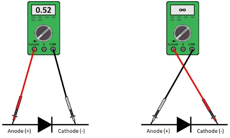
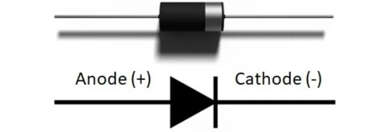
The test of diodes is reduced to checking their ability to pass current in only one direction. The measurement can be done with a multimeter. The diode check option is selected. If the multimeter doesn’t have this option, an ohmmeter is used. Measuring pipettes are connected to the diode ends. A correct diode conducts in one case, while in the other when the pipettes are replaced, it does not conduct. When the diode conducts in both directions, it is short-circuited; when it does not, it is open-circuit.
Alternator Diode Test with a Multimeter
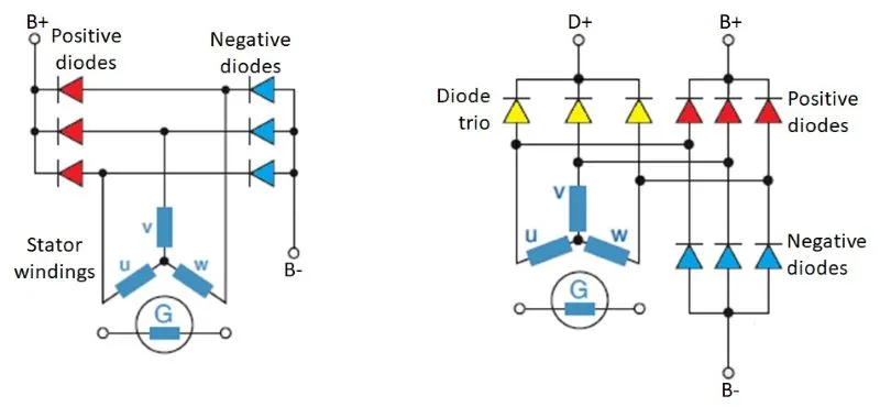
The diodes on the alternator are located on the diode board. Depending on the type, the alternator can have 6 (3 positive and 3 negatives) or 9 (3 positives, 3 negatives, and 3 exciting–diode trio) diodes.
Alternator with 6 and 9 diodes
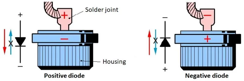
The plus and minus diodes are the main ones, and the entire vehicle system is powered through them. Positive and negative diodes are specially designed for easier assembly and cooling. With a positive diode, the housing is the cathode, and with a negative diode, the housing is the anode. When testing, you have to pay attention to which diode is positive and which is negative.
Alternator Main Diodes
A diode trio are excitation rectifier diodes, and on them, the ring indicates the cathode.
Alternator Excitation Diodes
Testing Diodes with a Multimeter
The multimeter is set to measure a diode or resistance. The main diodes are checked first. One measuring pipette is placed on the positive plate (B+), and the other touches all three leads for the stator windings. All three readings should be the same, conducting or not depending on the polarity of the measuring pipette. Then the pipettes are reversed, and the measurements are repeated. All three results should be the same and opposite of the previous measurements. Now the procedure is repeated when the measuring pipette is placed on the negative plate (B-). If two identical values are measured when changing the place of measuring pipettes, then that diode is defective and should be replaced.
Finally, the excitation diodes, if any, are tested. We check each diode separately through two measurements by crossing the pipettes. If we measure two identical values, that diode is faulty and needs to be replaced.
Alternator Diode Testing – Procedure
To perform the alternator diode test, follow these steps:


