Voltage drop testing
A voltage drop check is performed when an excessive voltage drop between the alternator and the battery is suspected, as it can cause power problems.
Depending on the location of the voltage drop, we have two types of faults.
When there is a voltage drop at the terminals, the battery is insufficiently charged, regardless of the correct operation of the alternator.
Another case is when there is a voltage drop on the alternator, the battery is overcharged and overheated because the voltage at the alternator output is too high.
So, if the voltage drop is on the battery, the charging voltage is lower, and if it is on the alternator, overcharging occurs. That is why it is necessary to test all conductors and connections for voltage drop.
Voltage drops can occur anywhere in the output current and ground circuit but are particularly common at terminals and connectors due to the high charging current that passes through them. Even a small amount of resistance can cause a significant voltage drop when carrying a higher supply current.
A voltmeter is used to test the voltage drop. A voltmeter with a min/max range measurement option is very useful for measuring voltage drop, as it will record and retain the maximum voltage drop that occurs for a given duty cycle. Voltage drop tests are only valid when the circuit is under load, as voltage drop can only be measured when the current is flowing. A higher current flow causes a higher voltage drop at the point of the transient resistance. Therefore, the voltage drop test should always be performed when the circuit is under load.
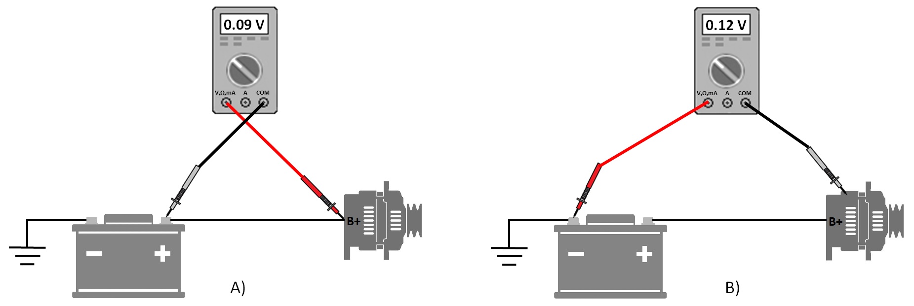
Checking the voltage drop on the plus (A) and minus (B) leads
A voltmeter is connected in parallel across the component, cable, or connection to be tested for voltage drop. It is usually most efficient to first measure the voltage drop across the positive and the negative side, and if necessary narrow down the test to individual components to determine exactly where the excessive voltage drop is located. For example, you can connect a red measuring pipet to the B+ output of the alternator and a black one to the positive terminal of the battery. Then put a heavy load on the charging system by turning on as many electrical devices as possible or using a load tester and read the voltage drop. Turning on the headlights can be replaced by an additional load. Then perform the same test on the ground side from the negative battery terminal to the alternator case.
Any particular conductor or connection must not have a voltage drop greater than 0.2 V, while the total voltage drop on the entire system should be less than 0.5 V. The voltage drop to the ground must be less than 0.2 V. Voltage drop testing determines whether the battery, regulator, and alternator work at the same potential.
In the presence of a voltage drop, the circuit is opened to locate the point of transient resistance. Each wire and connection is checked.
For voltage drop testing, follow these steps: