Testing an Oxygen/Lambda sensor
An oxygen sensor is a sensor that monitors the composition of the fuel-air mixture by measuring the oxygen level in the exhaust gas. For stable engine operation and more efficient operation of the catalytic converter, the engine ECU corrects the composition of the mixture based on data from the oxygen sensor. In tandem with the main oxygen sensor, another one is installed to control the correctness of the catalytic converter.
Oxygen sensor
An oxygen sensor is of the galvanic type because it does not require power for its operation. However, for the sensor to measure, it must reach operating temperature. The operating temperature of the oxygen sensor is 350…850 °C. It uses hot exhaust gases for heating and contains a heater inside.
There are several types of oxygen sensors: two-step, planar wide-band and resistive. Most often, a jump-type oxygen sensor is used on vehicles, which, by a sudden change in voltage around the ideal value of the fuel-air mixture (λ=1), determines two states of a rich and a lean mixture.
A voltage characteristic of the oxygen sensor jumps depending on the composition of the air-fuel mixture
A two-step oxygen sensor consists of a sensor and a heater and is connected to the ECU via four wires. Two conductors are for powering the heater (plus and minus) and are usually white. The sensor part has a minus line (most often grey) and an output signal line (most often black).
Service life and chemical pollution lead to the ageing of the oxygen sensor, which results in slow regulation and correction of the mixture by the injection system. There is no way to check the general condition of the oxygen sensor, that is, to determine that there has been a shift of the operating characteristic to the region of the rich mixture. A faulty oxygen sensor leads to an impairment of the efficiency of the catalytic converter and the exhaust gas quality with increased fuel consumption. The manufacturer recommends that the oxygen sensor be checked every 30,000 km and replaced after 100,000 km.
Possible malfunctions of the oxygen sensor are:
– defective sensor
– sluggish (old) sensor
– interruption of the lines from the probe to the ECU
– heater out of order
– interruption of the heater’s power supply (open or short circuit of the lines)
– interruption of the heater’s power supply from the ECU
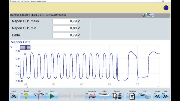
When light the malfunctioning indicator lamp is on the dashboard or when a malfunction of the oxygen sensor is suspected, ECU engine diagnostics are performed by reading stored fault codes and actual values. Through the ECU engine, we can check the current condition of the heater and the operation of the oxygen sensor. First, the output voltage oxygen sensor is measured when the engine is not running. Then the ECU takes a substitute value of 450 mV because the oxygen sensor is not functional. Start the engine. The oxygen sensor heated for 2…3 min at 2000 rpm. After heating, the oscillogram of the voltage signal from the oxygen sensor is recorded and analyzed. A correct oxygen sensor has an oscillation amplitude of 0.1 to 0.9 V and an oscillation frequency of at least one oscillation per second.
After diagnostics, the heater power supply is measured. Remove the socket from the oxygen sensor and measure the power supply coming from the ECU engine with the given contact. If there is no or insufficient power supply, continue by checking the condition of the lines from the socket to the ECU.
The next check relates to the condition of the oxygen sensor heater. The resistance of the heater is measured with an ohmmeter, and the measured value is compared with the one required from the information system for that oxygen sensor. If the heater is interrupted or the measured value is outside the specified range, it is necessary to replace the oxygen sensor.
Finally, the oscillogram of the output voltage signal of the oxygen sensor is recorded, which checks the state of the oxygen sensor. An oscilloscope is connected in parallel with the output connections on the oxygen sensor. First, the oxygen sensor is heated, and then the oscillogram of the output signal is recorded at 2000 rpm and idle. The amplitude signal should range from 0.1 to 0.9 V, and the frequency should have at least one full oscillation in one second.
When it is determined that the output signal of the oxygen sensor is outside the set value, the ECU of the engine adjusts the mixture incorrectly, we have a worse engine performance, increased fuel consumption and the quality of the exhaust gas is impaired because the efficiency of the catalytic converter is reduced. That is why it is necessary to replace the old oxygen sensor with a new one.
Oscillogram analysis of the oxygen sensor output signal
To test the oxygen sensor, follow these steps: