Vernier Caliper
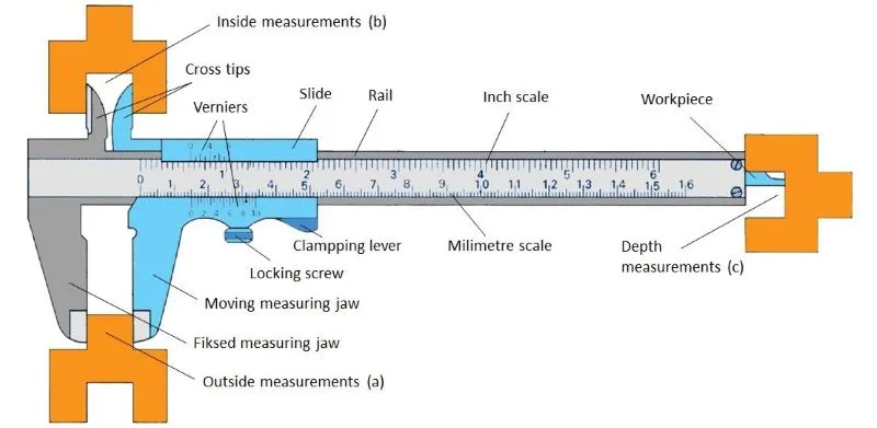
Vernier caliper is a measuring instrument used for measuring outside, inside (bore), and depth measurements. It consists of a fixed measuring ruler and a movable measuring scale that are parallel to each other and expressed in mm and inch (upper fixed scale). There is a rail on the upper and lower edge of the ruler. The moving part of the scale on which the vernier scale is located slides on the rail. This scale passes over millimeter and inch scales.
Vernier Caliper
A larger pair of measuring jaws measures outside dimensions (a). In the upper part, a smaller pair of measuring jaws crosses each other to measure an object’s inside dimension (b). When the slider is moved, a measuring rod comes out laterally to measure depth (c).
How to Use a Vernier Caliper
By moving the slider, the measuring edges are placed on the measuring object. With the help of the clamping lever and the locking screw, the movable scale can be stiffened to maintain the slider in position for accurate readings. The reading is performed by comparing the position of the vernier (moving) scale and the measuring scale on the ruler.
There is a millimeter scale on the fixed ruler. The smallest displayed value is 0.1 mm. The vernier (moving) scale defines the accuracy of the readings of the vernier caliper. The measured value (measurement accuracy) can be read to 1/10 mm = 0.1 mm; 1/20 mm = 0.05 mm and 1/50 mm = 0.02 mm. The vernier caliper in the picture above has a measurement accuracy is 1/10.
How To Read A Vernier Caliper
With a 1/10 vernier scale, 9 mm are divided into 10 sections. The vernier scale unit is thus 0.9 mm. Readings are thus possible to an accuracy of 1/10 mm. One-tenth of a millimeter is read over the vernier scale.
The reading of the measured value is performed first on a fixed millimeter scale and continues on the vernier scale. The value in millimeters is read up to the vernier scale. The decimal value is read on the vernier scale. When the lines on the millimeter and vernier scales coincide, the number on the vernier scale is the decimal value of the measured quantity.
Reading on the vernier scale of accuracy 1/10
The vernier scale with an accuracy 1/20, 39 mm is divided into 20 parts. In this case, the vernier graduation is 39 mm/20 = 1.95 mm, and the vernier accuracy is 2 mm – 1.95 mm = 0.05 mm = 1/20 mm.
Reading on the vernier scale of accuracy 1/20
Technicians often use vernier calipers to measure the length and diameter of bolts, the diameter of the shaft, the depth of blind holes in housings, the outside and inside dimensions of the bearings and the like.
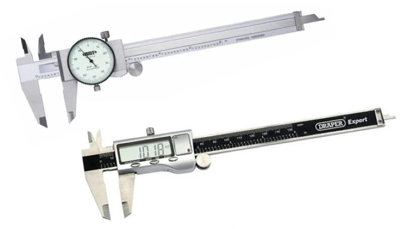
Newer versions of vernier calipers have dial and digital scales. The dial caliper has the main scale on the graduated bar, and fractional measurements are taken from a dial with a rotating needle. These tend to be easier to read than the older versions. More recently, digital scales on vernier calipers have become commonplace. The principle of their use is the same as any vernier caliper. However, they have a digital scale that reads the measurement directly. In both of these versions, it is necessary to zero the meter before starting the measurement.
Dial and Digital Calipers
Recommendations for Using a Vernier Caliper
Never try to measure the diameter of the shaft while it is rotating as it may injure you and damage the caliper. When measuring, ensure that the measuring surfaces are clean and apply the correct pressure by holding the caliper in the correct position. Start measuring the depth by first leaning on the side of the fixed ruler, and then pulling out the measuring rod. The measuring rod must be at a right angle because if it is beveled, you will get higher measured values. Do not use cross-tips for scribing.


