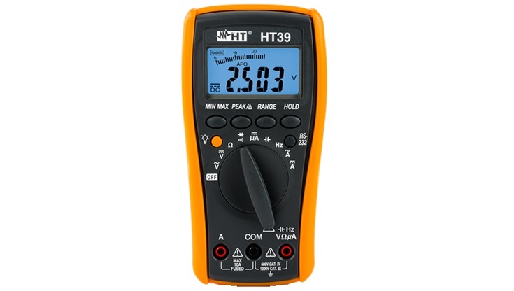
Multimeter
A multimeter is an electrical measuring instrument for measuring DC and AC voltage, current, and resistance. More advanced multimeters can measure other quantities such as temperature, capacitance, frequency, state of diodes and transistors, engine speed, pressures, etc. To the way the measured value is displayed, there are multimeters with analog and digital indicators.
Analog multimeter
The analog multimeter uses a moving coil meter that moves above the measuring scale. The position of the pointer (needle) shows the value of the measured quantity on the scale.
The instrument has different measuring ranges. The selection of the type of measurement and the measuring range is done with a range selector switch. Before measuring, based on the measured quantity, probes are connected to the appropriate multimeter ports. It selects the type of measurement (DC or AC), electrical measurement quantity (voltage, current, or resistance), and measuring range via the range selector switch. If we are not sure what the expected value of the electrical quantity is, we start from the largest range and reduce it until we get a deviation of the pointer that is readable. Otherwise, we can destroy the multimeter. Also, we have to pay attention to the polarity because the pointer will move in the opposite direction, which can cause a malfunction of the measuring device.
Analog multimeter
An analog multimeter measures resistance by measuring the current flowing through a resistor. Therefore, the accuracy of the resistance measurement depends on the condition of the battery in the multimeter. Before each resistance measurement, the instrument must be calibrated to zero. Probes are short-circuited and the pointer is set to zero via the rheostat. When measuring resistance, the current through the resistor is small. When measuring infinitely large resistance, there is no movement of the pointer, and when the resistance value is zero, we have a full deviation. The resistance scale is nonlinear and opposite to the voltage and current scale.
The reading is performed on the appropriate scale for a given measuring quantity and measuring range. When viewing the meter, the eye should be at right angles to the plane of the meter back markings, i.e. looking directly at the meter. If you look at an angle there is an error in reading known as parallax errors.
Digital multimeter
A digital multimeter is much more accurate and easier to use than an analog multimeter. When measuring an electrical quantity, it is necessary to select the type and range and the numerical value of that quantity will be shown on the digital display. With some digital multimeters, the measuring range is adjusted automatically.
One of the advantages of this instrument compared to analog is that it is not sensitive to changes in measurement polarity due to incorrect connection. If the polarity is reversed, the measured value is shown on the digital display with a minus sign, which informs us about the polarity.
Digital multimeters have many additional capabilities for measuring and analyzing measured values. In addition, they can measure other physical quantities. Due to their advantages, they completely pushed analog multimeters out of use.
Using multimeters
DC voltage measurement (a) is performed by selecting the appropriate DC voltage measurement range (V=) on the selector switch. The black (common) measuring probe is connected to COM port and the red one to V/Ω port. The red probe is typically connected to the positive side of the circuit being tested, and the black probe to the negative post of the battery, or good ground. The DC voltage display shows the value of the DC voltage.
AC voltage measurement requires that the selector switch be placed in the AC voltage measurement position (V~) and it does not matter how we place the probes. Measuring AC voltage always gives positive values no matter how we connected the probes.
Current measurement (b) is performed by selecting a range for current measurement on the selector switch, and a choice of DC or AC. The black probe is connected to the COM port, and the red probe, depending on the expected value of the current, to the connection for measuring low or high current port. If direct current is measured, then the red probe is connected to the disconnected circuit at the end of the plus power supply, and the black to the other end. When measuring alternating current, the arrangement of probes when connecting is not important. Pay attention to the measuring range because too much current can destroy the measuring instrument.
Resistance measurement (c) requires that a range for resistance measurement (Ω) be selected on the selector switch. Connect probes to COM and Ω. If you need to measure resistance in a circuit, always make sure the power is disconnected. Connecting an ohmmeter into a live circuit usually results in damage to the meter.
We place the ends of probes on the leads of the measuring object and the instrument shows us the value of resistance. This option is often used to check for interruptions and short circuits. By selecting this option, an acoustic signal is heard on the switch in the event of a short circuit, and it is absent when interrupted.
Measuring voltage, current and resistance


