Mode sensors
Mode sensors inform the electronic control unit (ECU) about the current state (on or off) of a device, function, or system on the vehicle.
Based on the data from the mode sensor, the ECU monitors whether the monitored system is on or off. Also, when the ECU gives the order to turn on/off a device, it receives feedback from the mode sensor as to whether its order is executed.
There are various examples of the use of mode sensors on vehicles:
– lighting on the vehicle;
– turning on stop lights when pressing the brake pedal (ECU ABS or lighting);
– starting of air conditioners (ECU engine, air conditioning);
– detection of the door, trunk, and hood opening (ECU central electronics);
– detection of fastening of seat belts (ECU airbag);
– parking brake release detection (ECU ABS, engine);
– determining the position of the gear lever (ECU engine, gearbox);
– detection of pressing the clutch pedal (ECU engine, gearbox);
– determining the position of the throttle valve at idle speed, etc. (ECU engine).
Condition sensors exist as:
– button
– switches
Brake pedal button Vehicle lighting switch
We distinguish mode sensors with positive and negative power supplies.
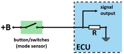
A mode sensor with a positive supply on one port has a permanent plus, while the other port is via a conductor connected to the ECU.
Connecting mode sensor with positive power supply and ECU
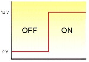
When the switch/button is open (OFF), the ECU input disconnect from the plus power supply (+B). Then the output (control) point ECU is at the mass potential. Since the output voltage is equal to 0 V, the electronic control unit recognizes the state of the sensor – OFF.
When the switch/button is closed (ON) the plus power supply is supplied to the ECU input via the switch/button. The resistor (R) separates the mass from the input voltage, so the output signal is equal to the supply +B, which corresponds to the state of the sensor of the controlled device – ON.
Open/closed (OFF/ON) mode of the sensor with the positive supply
Possible malfunctions in the operation of the mode sensor are:
– defective switch/button
– sensor power open circuit (in this case +B)
– open circuit between the sensor and ECU
– interruption of the power supply from the ECU (in this case minus – ground)
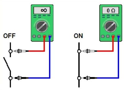
Testing the correctness of the mode sensor is performed with an ohmmeter when the system is without power or when the sensor is disconnected. The resistance at the terminals is measured when the button/switch is open and closed. When the button/switch is open (OFF), the measured resistance should be infinite, and when it is closed (ON) 0 Ω.
Mode sensor test
After checking the sensors, test the power supply. In the case of mode sensors with a positive power supply, the sensor comes from the mains plus supply (+B) and the ECU minus.
Finally, the output signal sent to the ECU is measured. The measurement is performed with a voltmeter or oscilloscope. When the sensor (button/switch) is open the output signal is 0 V. When it is closed, the ECU value of the voltage signal is equal to the supply voltage +B.
Mode sensor output signal with the positive supply


