Rack and pinion replacement

Rack and pinion replacement is done after inspecting all parts of the system to ensure that the problem is in the rack assembly. Many symptoms, such as wear, play, and rough or uneven steering, can indicate a malfunctioning rack assembly. Regardless of the symptoms, all other steering problems should be considered and eliminated before removing or replacing the rack.

Because these systems vary by vehicle type and manufacturer design, there is no uniform removal and replacement procedure, so the following steps are non-specific. Before replacement, refer to service information and the appropriate repair manual.

After reviewing the service information, start the engine and straighten the wheels. After turning off the engine, it is necessary to lock the steering column (steering wheel). This will keep the clock spring in a neutral position after the post is released, as it will not be able to rotate freely and damage the spool. Lift the vehicle with a hoist, and remove the front wheels.

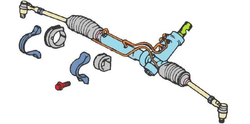
Car rack and pinion replacement. Graphical representation of the elements to be removed before removing the rack and pinion.

Removing and Replacing Rack and Pinion

First, the universal joint coupling is separated from the rack pinion shaft by removing the bolt or pin. If the same rack assembly is mounted, the coupling and pinion shaft are marked with paint before separation.

Then the hoses of the steering system are separated. Place an oil catch container under the power steering rack. Plug them to keep fluid from leaking.

After separating the steering wheel, move on to separating the outer tie-rod ends of the clamp from the knuckle. The cotter pins and nuts from the end of the tie rods are removed using an adjustable puller, fork, or hammer to remove the tie rod from the sleeve.

Finally, by removing the mounting screws of the bracket and bushings, the rack-and-pinion is released. Mark the position of the brackets and bushings if the same rack assembly is mounted. Due to its length, it is easiest to pull the rack-and-pinion assembly out through the vehicle’s wheel well.

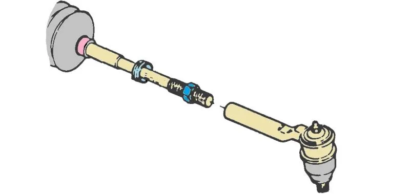
Car steering system Tie rods. Graphic representation and description of Tie rods.

Tie Rods

When removing the tie rod ends for reuse, record the number of turns during removal.

An assembly of the rack is in reverse order. After mounting all the elements, it is necessary to perform wheel alignment.

Rack and Pinion Replacement Instructions

To rack and pinion replacement, follow these steps:

Mask-Step-Rack and Pinion Replacement

Preparation Before Removing the Rack and Pinion

Read the instructions and repair manual. Start the engine and straighten the wheels. Turn off the engine and lock the steering column (steering wheel). Raise the vehicle with a hoist and remove the drive wheels. Prepare a container to collect the leaking steering fluid.

Mask-Step-Rack and Pinion Replacement

Removing the Rack and Pinion

Mark the position of the joint coupling and the rack pinion shaft. Remove the bolt or pin and separate the joint coupling from the rack pinion shaft. Place the container under the rack and separate the hoses of the steering system from the rack. Plug the ends of the separated hoses. Remove the cotter pins and nuts from the end of the tie rods. Use a suitable tool to separate the tie rod ends of the clamp from the wheel sleeves. Remove the bracket and bushings rack and pinion. Mark the position of the bracket and bushings. Pull the rack-and-pinion assembly out through the vehicle’s wheel well.

Mask-Step-Rack and Pinion Replacement

Assembly of the Rack and Pinion

Assembly is done in reverse order. Insert the rack assembly through the vehicle’s wheel well. Place and tighten the rack using brackets and bushings. Connect and secure the joint of the tie rod end and the wheel sleeve. Connect the hoses of the steering system to the rack control box. Connect and secure the joint coupling of the steering column and the gear shaft. Mount the wheels. Add steering fluid and perform the procedure of bleeding from the steering system. Lower the vehicle and check the operation of the steering system.

See also

The image is a link to the page where the procedure for the Cranking compression test is described. The picture shows an engine where a black hose is placed in the place of one spark plug, at the other end of which is a white manometer for measuring the pressure in the cylinder. In the lower part of the picture, on the gray bar, it says in large white letters, "Cranking compression test".
Alternator stator testing on the workbench for open, short circuit, and ground connections. the alternator stator with windings is disassembled in the picture. In the lower part of the picture, on the gray strip, it says in large white letters, the test of the Alternator stator testing.
Engine intake manifold testing for false air by spraying with soapy water. In the lower part of the picture, on the gray strip, it says in large white letters the Engine intake manifold testing.

Video recommendation