Oscilloscope alternator test
One of the faster ways to check an alternator is an oscilloscope test. The resulting oscillogram gives us an insight into the alternator’s correctness and directs us towards further testing and finding the cause of the failure.
An oscilloscope recording of the alternator output voltage can determine the existence of an alternating component. All electrical components on the vehicle operate on DC voltage. Often, an alternating component in the power supply can block their operation. It happens that you replace a “faulty” electronic component, and then you find that the new one does not work either. That’s a sign to record an oscillogram of the alternator output voltage.
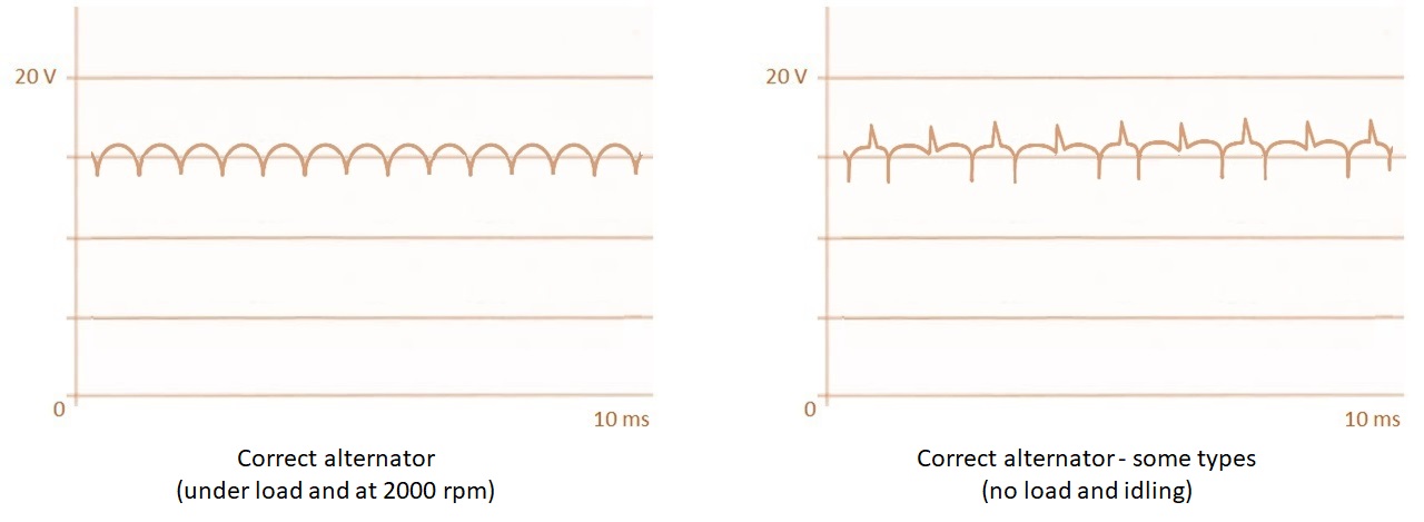
The plus probe of the oscilloscope is connected to the plus output of the alternator (B+), and the minus probe to the ground. The oscilloscope is set to measure alternating voltage in the range of up to 20 V. The time axis is set to 10 or 20 ms. The output signal of the alternator is recorded under a load of 15 A and at 2000-2500 rpm. With some types of alternators in good condition without load, it has an unusually high voltage peak, but under load it is good. For the load, it is enough to turn on the headlights and some additional devices.
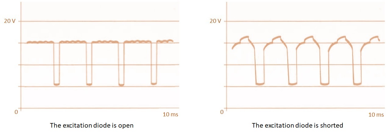
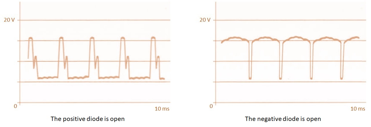
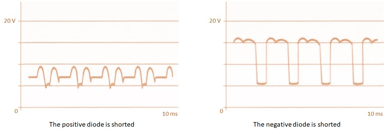
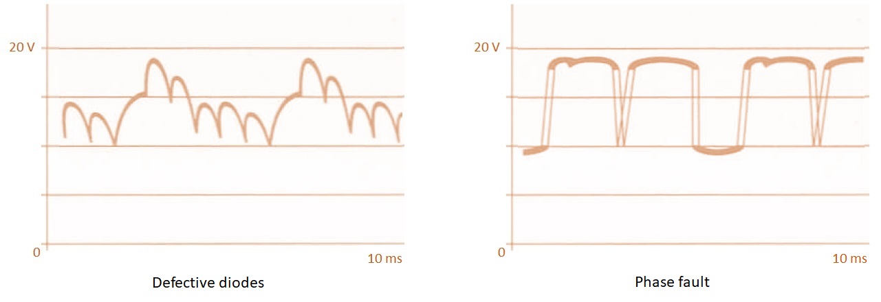
The following pictures show examples of recorded oscillograms with a description of the state of the alternator.


