Alternator stator testing
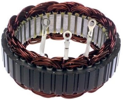
Testing the correctness of the stator winding of the alternator is performed visually and by measuring the resistance. The visual inspection looks for changes in color or damage to the windings. Often due to excessive heat, parts of the winding insulation are deformed. A quick check of the condition of a suspicious part of the winding is to scrape the winding with a knife blade. If the varnish falls off, the winding insulation is damaged. In the same way, the connections on the stator are also checked. Any signs of damage indicate that the stator is faulty.
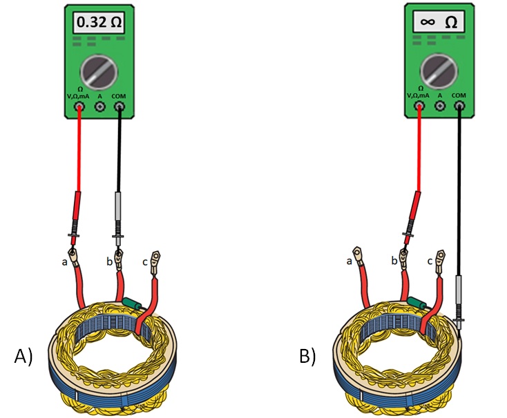
If the stator passes the visual inspection, it is approached testing of windings for open-circuit, and short to ground. The electrical check is done with an ohmmeter. As the stator has three windings connected in a star, there are three leads (a, b, and c). Resistance measurement is performed between two leads in each combination (a-b, a-c, and b-c). The measured coil resistance should be less than 0.5 Ω. If infinite resistance is measured between any two terminals, the winding is broken and the stator is replaced.
Testing windings for open-circuit (A) and short-to-ground (B)
An ohmmeter is connected between the stator housing and the winding terminal to test for a short-to-ground. With good winding insulation, the ohmmeter shows infinite resistance across all three windings. If at least one winding shows some resistance, the insulation of that winding has broken, it is short-to-ground and the stator is replaced.
To perform an alternator stator winding test, follow these steps:


