MAP sensor test
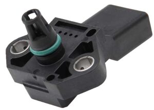
The control units of the injection system to determine the amount of injected fuel and the formation of the combustion mixture require a constant flow of data on the mass of the intake air. One way to determine the air mass is to measure the absolute pressure of the intake manifold during engine operation. A MAP (Manifold Absolute Pressure) sensor measures air pressure in the intake manifold. In combination with the MAF (mass flow sensor), the MAP sensor controls the operation of the EGR valve.
MAP sensor
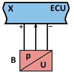
Regardless of MAP sensor type (capacitive, resistive tensometric, or piezoelectric) procedure for correctness testing is the same. For its operation, the MAP Sensor requires a constant power source of 5 V, which it receives from the ECU via two conductors (plus and minus). The third conductor is for the output signal of the measured pressure value from the MAP sensor to the ECU.
Map sensor circuit
The electronic control unit powers the sensor and constantly monitors its operation. If the ECU registers a malfunction, it stores the fault code and lights the malfunction indicator lamp on the dashboard. The ECU can detect a sensor malfunction, sensor circuit faults, damage, contamination, or poor sealing in the intake manifold. Electrical faults are registered, power failure, short circuits, and interruption of the output signal supply from the MAP sensor in the intake manifold.
First, system diagnostics and fault code reading are performed. If there is a fault for the MAP sensor stored in the fault memory, this is the starting point from which to start the sensor test. Next, as part of the diagnostics, the actual values from the MAP sensor are read and compared with the required ones from the information system. In the end, recording and analysis of the oscillogram of the MAP sensor’s operation as seen by the ECU is performed. This recording is done during idling, gentle acceleration and accelerator pedal release, and sudden acceleration. Oscillogram analysis checks the response of the MAP sensor to changes in the operating mode and the accuracy of the air pressure readings in the intake manifold.
After diagnostics, the power supply is checked. In the information system, we get acquainted with the electrical connection diagram, the arrangement of pins on the sensor socket, the required range of supply voltage, and possibly the recommended test procedure. The measurement of the sensor’s power supply is performed with the given contact on the switch near the steering wheel. If there is no voltage, the power supply has been interrupted, and the causes can be: the opening of the plus and/or minus line, a short circuit, or an interruption of the power supply in the ECU. If the measured voltage is lower than the required value, check all connections from the ECU to the sensor for voltage drop due to poor contact, dirt, or corrosion.
The next check is related to measuring the output voltage on the MAP sensor itself. It is estimated when the engine is not running, idling and possibly (if data is available) at 2000 rpm. The output voltage values obtained are compared with the actual ones from the information system for that vehicle and the MAP sensor. If the measured values do not correspond to the set values, removing the MAP sensor and performing additional tests on the workbench are necessary. After this check, we can determine precisely whether the MAP sensor or the engine is faulty.
This measurement checks the reaction of the MAP sensor to changes in the engine operating mode. Over time, after long-term use, impurities (dirt, oil, fuel, etc.) accumulate on the measuring part inside the sensor, preventing direct contact between the intake air and the meter. Therefore, the MAP sensor cannot keep up with the constant changes in the operating mode, and a delayed measurement occurs. When we have such a case, it is necessary to eliminate malfunctions that lead to the appearance of impurities in the intake pipe and replace the old MAP sensor with a new one.
To test the MAP sensor, follow these steps:


